

Introduction to finite state machines for firmware development
In the preceding article, we talk about design patterns in firmware development and we noticed that there are some cases where the system needs to remember the state it is on. In this report, we are going to go deeper into the Finite State machine pattern.
What is a Finite State Machine
A Finite State Machine is a system representation. It models the system using States and Events, in that way if some event happened the system is going to respond to it by doing something and maybe changing its state. If the state machine has a finite number of states we call it a Finite State Machine (FSM).
Let’s consider the simplest example: A Bulb that turns on and off when a button is pressed.
                +----------+
                |          |
 Switch ---------  System  -------- Light
                |          |
                +----------+
For this case, the system has two states (On and Off) and just one event (switch pressed), consequently the FSM that represents this system could be something like this:

Let’s proceed with the system described in the previous article, a blinking led that changes its frequency according to two push buttons (+ and -):
                              +---------------------------+
                              |                           |
                              |                           |
 + Button ---------------------                           --------------------  LED
                              |                           |
                              |          System           |
                              |                           |
                              |                           |
 - Button ---------------------                           |
                              |                           |
                              +---------------------------+
In this case, the FSM has two states (On and Off), but has three events (Switch, Minus Button pressed and Plus Button Pressed). The FSM that represents this system is:

A system can have multiple FSMs working concurrently with a large number of States and Events in real life. We are going to go further into the following articles.
Finite State Machines C implementation
A simple Finite State machine can be implemented in two ways:
– A switch case for the states with switch cases (or ifs) for the events
– A switch case for the events (or ifs) with switch cases for the states
States switch case
For this section we are going to use the latest system:
events.h file:
//Events declaration
#define NO_EVENTS          0b00000000
#define SWITCH_EVENT        0b00000001
#define MINUS_BUTTON_EVENT 0b00000010
#define PLUS_BUTTON_EVENT  0b00000100
states.h file:
//States declaration
#define ON_STATE   0
#define OFF_STATE  1
main.c file:
// Specific include directives:
#include “includes.h”
#include "events.h"
#include "states.h"

//Varibles initialization
uint16_t delayValue = 1000;
bool aliveLed = HAL_GPIO_INIT(PIN_0, OUTPUT);
uint8_t currentEvent = NO_EVENTS;
uint8_t currentState = OFF_STATE; //Initial state

//ISR Functions
void blinkLed() {
  START_TIMER_INTERVAL(delayValue, blinkLed); // Run the interval again with the delayValue
  currentEvent = currentEvent | BLINK_EVENT;
}

void isrMinusButtonFunction() {
  currentEvent = currentEvent | MINUS_BUTTON_EVENT;
}

void isrPlusButtonFunction() {
  currentEvent = currentEvent | PLUS_BUTTON_EVENT;
}

//Callback functions
void setLedValue(bool led) {
  aliveLed = led;
}

void callbackMinusButtonEvent() {
  delayValue = delayValue + 100;
}

void callbackPlusButtonEvent() {
  delayValue = delayValue - 100;
}


int main(void) {
  // Initialization or Setup

  HAL_MCU_INIT();
  HAL_GPIO_INIT(PIN_1, INPUT_CHANGE); // - button
  HAL_GPIO_INIT(PIN_2, INPUT_CHANGE); // + button
  TIMERS_INIT();

  HAL_SET_ISR(PIN_1, isrMinusButtonFunction); //Set the callback function for PIN_1 change state
  HAL_SET_ISR(PIN_2, isrPlusButtonFunction);  //Set the callback function for PIN_2 change state
  START_TIMER_INTERVAL(delayValue, blinkLed); //Set the callback function for the blinking function

  while (1) {
    switch (currentState) {
      case ON_STATE:
        if ((currentEvent & SWITCH_EVENT) != 0) {
          setLedValue(true);
          currentState = OFF_STATE; //Change the state
        }
        if ((currentEvent & MINUS_BUTTON_EVENT) != 0) {
          callbackMinusButtonEvent();
        }
        if ((currentEvent & PLUS_BUTTON_EVENT) != 0) {
          callbackPlusButtonEvent();
        }
        break;
      case OFF_STATE:
        if ((currentEvent & SWITCH_EVENT) != 0) {
          setLedValue(false);
          currentState = ON_STATE; //Change the state
        }
        if ((currentEvent & MINUS_BUTTON_EVENT) != 0) {
          callbackMinusButtonEvent();
        }
        if ((currentEvent & PLUS_BUTTON_EVENT) != 0) {
          callbackPlusButtonEvent();
        }
        break;
    }
    currentEvent = NO_EVENTS;
  }
  return 0; // No error
}
As the reader can verify the source is more extensive, but it allows to discard events that can not happen in a specific state.
Events switch case (or if)
For this section we are going to use the latest system:
events.h file:
//Events declaration
#define NO_EVENTS          0b00000000
#define SWITCH_EVENT        0b00000001
#define MINUS_BUTTON_EVENT 0b00000010
#define PLUS_BUTTON_EVENT  0b00000100
states.h file:
//States declaration
#define ON_STATE   0
#define OFF_STATE  1
main.c file:
// Specific include directives:
#include “includes.h”
#include "events.h"
#include "states.h"

//Varibles initialization
uint16_t delayValue = 1000;
bool aliveLed = HAL_GPIO_INIT(PIN_0, OUTPUT);
uint8_t currentEvent = NO_EVENTS;
uint8_t currentState = OFF_STATE; //Initial state

//ISR Functions
void blinkLed() {
  START_TIMER_INTERVAL(delayValue, blinkLed); // Run the interval again with the delayValue
  currentEvent = currentEvent | BLINK_EVENT;
}

void isrMinusButtonFunction() {
  currentEvent = currentEvent | MINUS_BUTTON_EVENT;
}

void isrPlusButtonFunction() {
  currentEvent = currentEvent | PLUS_BUTTON_EVENT;
}

//Callback functions
void setLedValue(bool led) {
  aliveLed = led;
}

int main(void) {
  // Initialization or Setup

  HAL_MCU_INIT();
  HAL_GPIO_INIT(PIN_1, INPUT_CHANGE); // - button
  HAL_GPIO_INIT(PIN_2, INPUT_CHANGE); // + button
  TIMERS_INIT();

  HAL_SET_ISR(PIN_1, isrMinusButtonFunction); //Set the callback function for PIN_1 change state
  HAL_SET_ISR(PIN_2, isrPlusButtonFunction);  //Set the callback function for PIN_2 change state
  START_TIMER_INTERVAL(delayValue, blinkLed); //Set the callback function for the blinking function

  while (1) {
    if ((currentEvent & SWITCH_EVENT) != 0) {
      switch (currentState) {
        case ON_STATE:
          setLedValue(true);
          currentState = OFF_STATE; //Change the state
          break;
        case OFF_STATE:
          setLedValue(false);
          currentState = ON_STATE; //Change the state
          break;
      }
    }
    if ((currentEvent & MINUS_BUTTON_EVENT) != 0) {
      callbackMinusButtonEvent();
    }
    if ((currentEvent & PLUS_BUTTON_EVENT) != 0) {
      callbackPlusButtonEvent();
    }
    currentEvent = NO_EVENTS;
  }
  return 0; // No error
}
In this case, the source is shorter but this is just because in this specific example two events happen in all the states, so there is no reason to verify the state in those two events.
A more realistic example
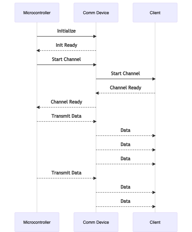
Let’s suppose that we are writing the firmware for a communication device, the microcontroller must initialize the device, then if everything goes fine, some handshake must start with another client to establish a channel. If the channel is ok the system can transmit data.
Below is a sequence diagram of correct behavior:
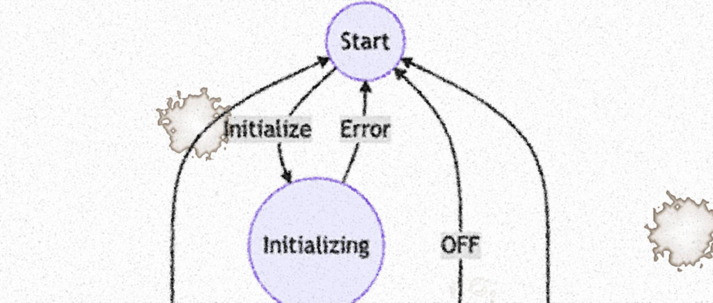
A Finite State Machine for the firmware running in the microcontroller is:
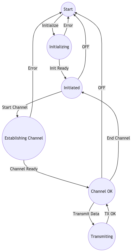
As the reader can verify not all the states respond to the same events, this behavior is very difficult to implement with an event handling pattern.
The source code for this FSM could be:
events.h file:
//Events declaration
#define NO_EVENTS            0b0000000000000000
#define INITIALIZE_EVENT     0b0000000000000001
#define INIT_READY_EVENT     0b0000000000000010
#define START_CHANNEL_EVENT  0b0000000000000100
#define CHANNEL_READY_EVENT  0b0000000000001000
#define TRANSMIT_DATA_EVENT  0b0000000000010000
#define TX_OK_EVENT          0b0000000000100000
#define END_CHANNEL_EVENT    0b0000000001000000
#define OFF_EVENT            0b0000000010000000
#define ERROR_EVENT          0b1000000000000000
states.h file:
//States declaration
#define START_STATE                 0
#define INITIALIZING_STATE          1
#define INITIATED_STATE             2
#define ESTABLISHING_CHANNEL_STATE  3
#define CHANNEL_OK_STATE            4
#define TRANSMITING_STATE           5
main.c file:
// Specific include directives:
#include “includes.h”
#include "events.h"
#include "states.h"

//Varibles initialization
uint16_t currentEvent = NO_EVENTS;
uint8_t currentState = START_STATE; //Initial state
...
...

//ISR Functions
...
...

//Callback functions
...
...

int main(void) {
  // Initialization or Setup
  HAL_MCU_INIT();
  ...
  ...
  ...
  while (1) {
    switch (currentState) {
      case START_STATE:
        if ((currentEvent & INITIALIZE_EVENT) != 0) {
          // ... do what must be done
          currentState = INITIALIZING_STATE; //Change the state
        }
        break;

      case INITIALIZING_STATE:
        if ((currentEvent & INIT_READY_EVENT) != 0) {
          // .. do what must be done
          currentState = INITIATED_STATE;
        }
        if ((currentEvent & ERROR_EVENT) != 0) {
          // .. do what must be done
          currentState = START_STATE;
        }
        break;

      case INITIATED_STATE:
        if ((currentEvent & START_CHANNEL_EVENT) != 0) {
          // .. do what must be done
          currentState = ESTABLISHING_CHANNEL_STATE;
        }
        if ((currentEvent & OFF_EVENT) != 0) {
          // .. do what must be done
          currentState = START_STATE;
        }
        break;

      case ESTABLISHING_CHANNEL_STATE:
        if ((currentEvent & CHANNEL_READY_EVENT) != 0) {
          // .. do what must be done
          currentState = CHANNEL_OK_STATE;
        }
        if ((currentEvent & ERROR_EVENT) != 0) {
          // .. do what must be done
          currentState = START_STATE;
        }
        break;

      case CHANNEL_OK_STATE:
        if ((currentEvent & TRANSMIT_DATA_EVENT) != 0) {
          // .. do what must be done
          currentState = TRANSMITING_STATE;
        }
        if ((currentEvent & END_CHANNEL_EVENT) != 0) {
          // .. do what must be done
          currentState = INITIATED_STATE;
        }
        if ((currentEvent & OFF_EVENT) != 0) {
          // .. do what must be done
          currentState = START_STATE;
        }
        break;

      case TRANSMITING_STATE:
        if ((currentEvent & TX_OK_EVENT) != 0) {
          // .. do what must be done
          currentState = CHANNEL_OK_STATE;
        }
        break;
    }
    currentEvent = NO_EVENTS;
  }
  return 0; // No error
}
Conclusion
For most of the cases in firmware development, a simple event handler pattern is not optimal. Most of the hardware devices are state-driven systems. The developer must make decisions based on systems-specific states, a state-driven pattern must be used. The presented examples are just the beginning; in firmware development, we must work with multiple hardware devices, each of them with its own states, so multiple Finite State Machines must be orchestrated.
2 Responses
Hello! I simply wish to give you a big thumbs up for the excellent info you have right here on this post. I will be coming back to your web site for more soon.
Very nice blog post. I absolutely love this website. Keep writing!